Most, or at least many belts changes are done without measuring the valve timing. As you may have guessed by now, that isn’t really how I roll, so even though the car ran great before the belt change and I had no reason to think they weren’t set properly, I nevertheless decided to set the cam timing myself. I even measured the valve timing before removing the old belts, and they were fine (almost).
As a general rule, I need to convince myself that I know what I am doing before picking up a wrench, so a small refresher was in order. The goal is of course to get the cams turning in the right phase relative to the crankshaft, and the workshop manual indeed tells you what this phasing should be; but I’ll admit, it tool me 4-5 re-reads to grasp what was meant in the manual. Here is an interpretation of what the manual is saying.
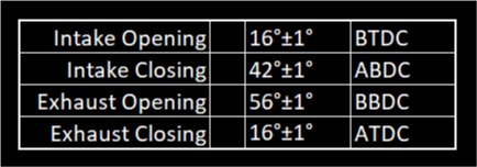
Table 9 on page B14 of the workshop manual defines the timing of the valve events : Intake Opening (I.O.), Intake Closing (I.C.), Exhaust Opening (E.O.), and Exhaust Closing (E.C) with respect to TDC and BDC and these are as follows:
So far, this only tells us when the events of intake and exhaust opening and closing happen relative to TDC, but did not anything about how much opening of the valve. Plotting the information that we have so far on a graph looks like this:

Then on page B15, Table 9/A gives the actual valve lift positions for a given crankshaft position (referenced to I.O. and E.C.). It gives 5 reference points (in 1 degree increments) which state valve lift relative to the I.O and E.C. events as described above.

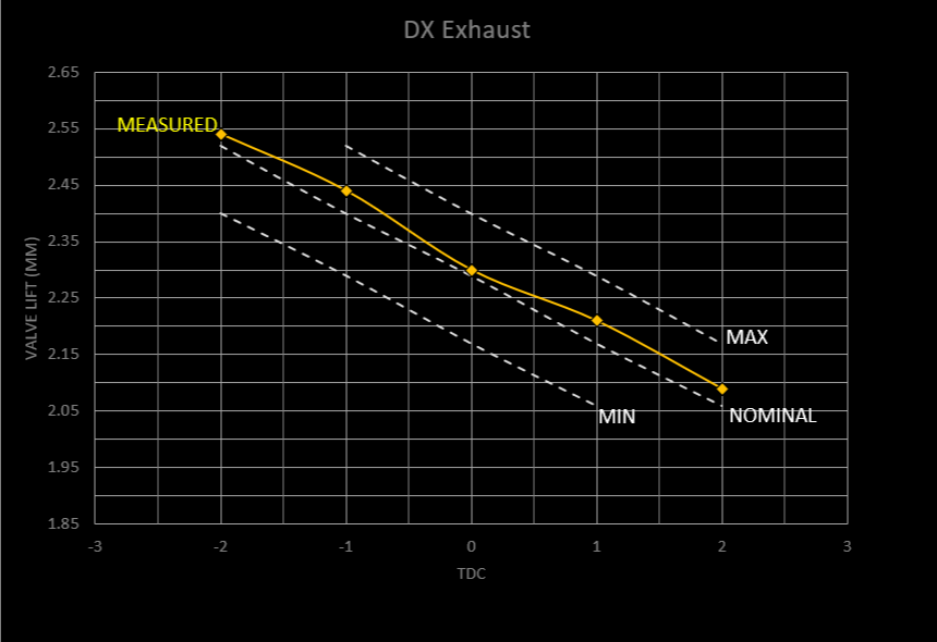
There is now sufficient information to fully define lift vs. crank position. Notice that the middle reference point (for the Intake cam for example) is 16 degrees after I.O. Referring back to table 9 the I.O. event is defined as happening 16 degrees before TDC; so the middle reference point is 16 degrees after I.O., and I.O is 16 degrees before TDC; so this reference point is (16 deg + (TDC - 16deg)), or simply TDC. This is nice because TDC is a directly measurable point. The graphs below show the relevant point for setting the cam timing which is TDC (and 2 degrees before and after). The graph on the right is the cleaned up version with error bars, and this is what we set the timing against.

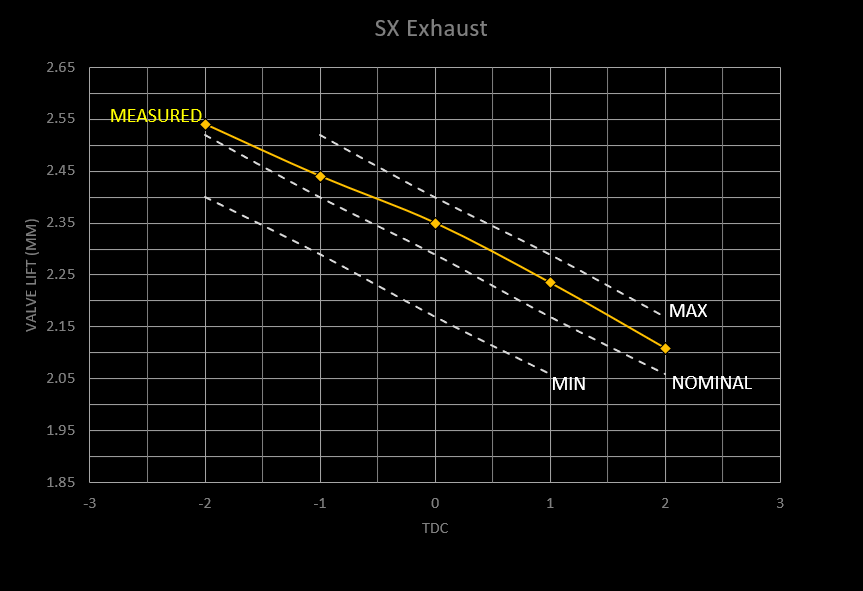
Now considering the exhaust cam, it is exactly the same thing, it is also referenced to TDC, the only difference being that the exhaust valve is closing whereas the intake valve is opening (so the slope will be negative as crank angle increase).
To adjust the timing, you need to set the valve lift vs. the crank angle (measured relative to TDC).
In order to measure the valve lift, you need to use a dial indicator (I used a digital indicator) and position it so that it touches a part of the cam tappet and is perpendicular to the surface of the tappet (or in line with the direction of tappet movement) for an accurate measurement. It is a bit tricky because the cam itself covers nearly the entire tappet. There is just barely enough tappet visible to position the indicator, and it helps to have a very fine needle point for the indicator.
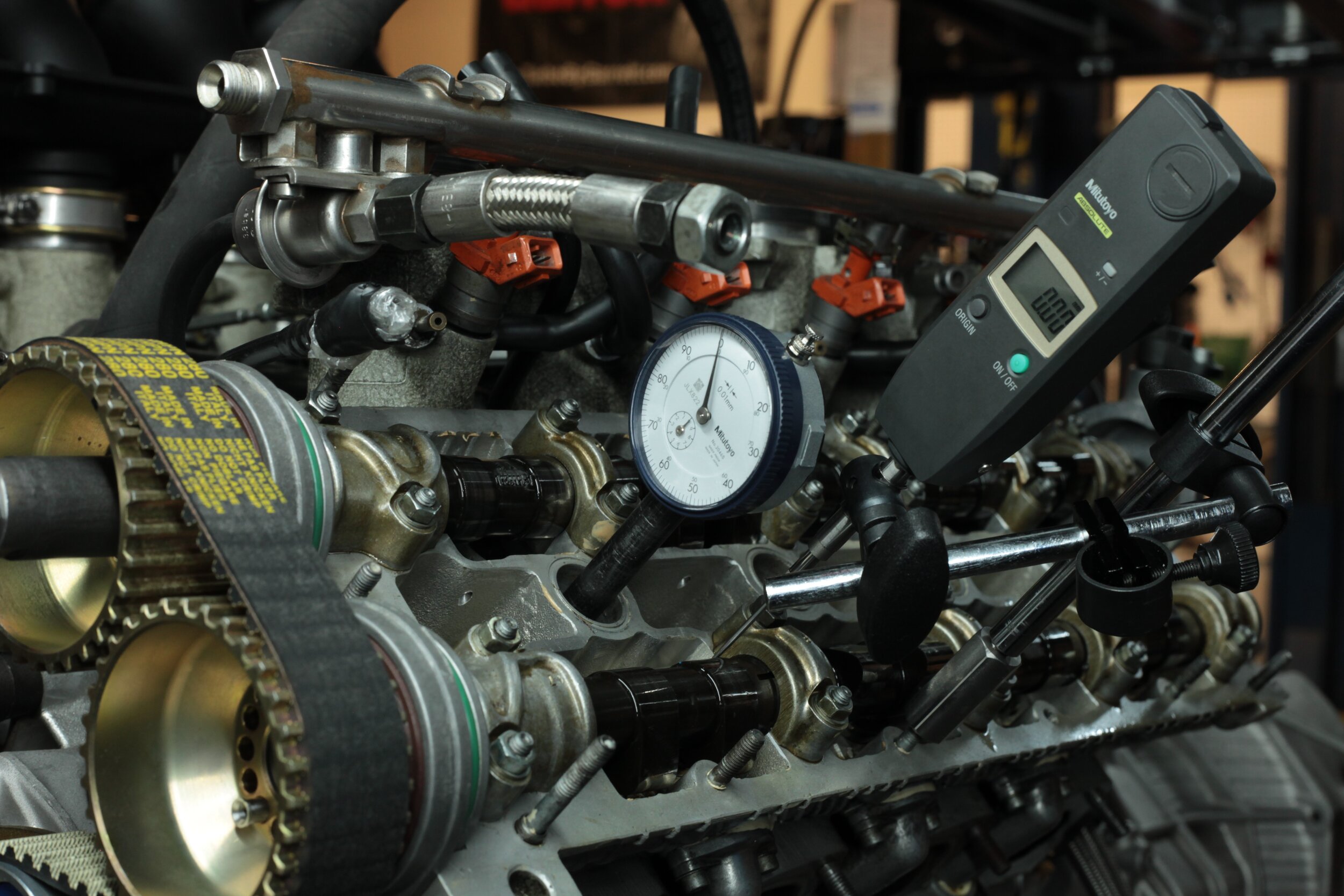
Second, in order to measure the crank angle, you will need either a degree wheel, or a second dial indicator which measures piston position through the sparkplug hole. The advantage of the degree wheel is that it allows you to easily measure the crank angles before and after TDC, whereas the dial indicator really just shows you TDC.
Of course the degree wheel needs to be set up with a pointer which is “adjusted” to TDC. There are several way to do this, and these are well documented processes, so I’ll leave that explanation to a quick YouTube search. I used the method which involves using as dead stop in the sparkplug hole, approaching it in two directions and then inferring TDC as the point in the middle.
Once the setup for measuring valve lift and crank angle is ready, then the fun begins. I started by rough setting the timing by aligning the marks on the cams while the crank is at TDC, which theoretically should already be pretty accurate. It is important to start “close” to the right timing to avoid the valve contacting a piston, which you don’t want even when turning the motor over by hand. Nothing specific to Ferrari here, and very common, so to get more info on this risk, just google “interference engine”
Adjustments are made by rotating the camshaft relative to it’s pulley, which is possible due to the clever Vernier hole setup on the cam pulleys.
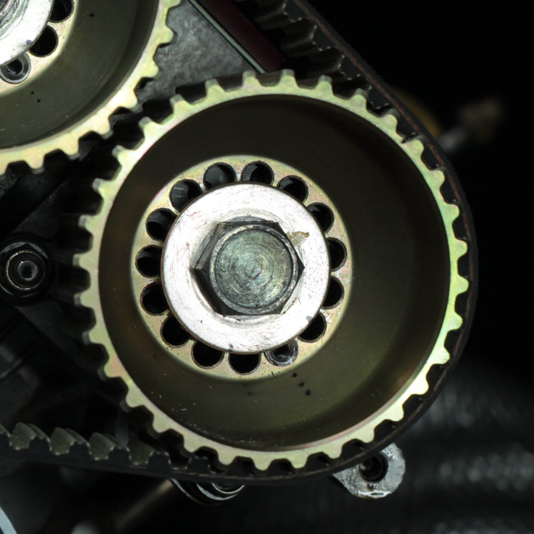
You can see that the series of holes in the pulley don’t all line up with the holes behind the pulley (which are on the camshaft itself), There is one set of holes that are aligned, which has the dowel pin in it. Removing the dowel pin and (slightly) rotating the pulley relative to the camshaft will align the adjacent hole and then of course the dowel can be inserted it that hole. The three dots in front of it are my own reference marks.
Pro Tip Use the dowel pin available from Superformance that has the threaded hole in it , it makes it MUCH easier to remove, as you can thread in a screw for some leverage to remove the pin, which is generally wedged in there quite tightly. The factory dowel has no threaded hole, and is very difficult to remove.
Moving the dowel pin to the next adjacent hole will move the pulley 1.5 degrees relative to the camshaft. Note that the tolerance on the valve opening / closing position is 2 degrees (+/- 1 degree), so there is likely only 1 dowel position that will fall “in spec”
After a lot of removal and repositioning of the dowel pins, then measuring and measuring again, I finally ended up with the following, repeatable measurements


Happy with the measurements, I once again checked the gap on the tensioners to make sure it was still 2.5mm, which it was.